
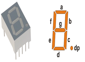
7 Segment LED Display:

Hardware connection:

Program:
1st method:
/** File: 3a_7SegmentLedDisplay.c
* Author: Udaya Prakash Jayaraman
* 7Segment led Display
*
* Circuitrcuit Connection
* Com anode type 7Seg LED Display
* RB0- a
* RB1- b
* RB2- c
* RB3- d
* RB4- e
* RB5- f
* RB6- g
* RB7- h
* Vcc- Resistor- COM
*
* Created on June 3, 2019, 2:23 PM
*/
#define _XTAL_FREQ 8000000
#pragma config FOSC = HS // Oscillator Selection bits (RC oscillator)
#pragma config WDTE = OFF // Watchdog Timer Enable bit (WDT enabled)
#pragma config PWRTE = OFF // Power-up Timer Enable bit (PWRT disabled)
#pragma config BOREN = OFF // Brown-out Reset Enable bit (BOR enabled)
#pragma config LVP = OFF // Low-Voltage (Single-Supply) In-Circuit Serial Programming Enable bit (RB3/PGM pin has PGM function; low-voltage programming enabled)
#pragma config CPD = OFF // Data EEPROM Memory Code Protection bit (Data EEPROM code protection off)
#pragma config WRT = OFF // Flash Program Memory Write Enable bits (Write protection off; all program memory may be written to by EECON control)
#pragma config CP = OFF // Flash Program Memory Code Protection bit (Code protection off)
// #pragma config statements should precede project file includes.
// Use project enums instead of #define for ON and OFF.
#include <xc.h>
#include <pic16f877a.h>
void DELAY(unsigned int Count)
{
unsigned int i,j;
for(i=0;i<Count;i++)
{
for(j=0;j<1000;j++);
}
}
int main() {
/* Configure the ports as output */
TRISB = 0x00;
while (1)
{
PORTB = 0xc0;
DELAY(100);
PORTB = 0xf9;
DELAY(100);
PORTB = 0xa4;
DELAY(100);
PORTB = 0xb0;
DELAY(100);
PORTB = 0x99;
DELAY(100);
PORTB = 0x92;
DELAY(100);
PORTB = 0x82;
DELAY(100);
PORTB = 0xf8;
DELAY(100);
PORTB = 0x80;
DELAY(100);
PORTB = 0x90;
DELAY(100);
}
}
2nd Method:
/*
* File: 3b_7SegmentLedDisplay.c
* Author: Udaya Prakash Jayaraman
* 7Segment led Display
*
* Circuitrcuit Connection
* Com anode type 7Seg LED Display
* RB0- a
* RB1- b
* RB2- c
* RB3- d
* RB4- e
* RB5- f
* RB6- g
* RB7- h
* Vcc- Resistor(value based on led supply, approx 100ohms resistor)- COM
*
* Created on June 3, 2019, 2:23 PM
*/
#define _XTAL_FREQ 8000000
#pragma config FOSC = HS // Oscillator Selection bits (RC oscillator)
#pragma config WDTE = OFF // Watchdog Timer Enable bit (WDT enabled)
#pragma config PWRTE = OFF // Power-up Timer Enable bit (PWRT disabled)
#pragma config BOREN = OFF // Brown-out Reset Enable bit (BOR enabled)
#pragma config LVP = OFF // Low-Voltage (Single-Supply) In-Circuit Serial Programming Enable bit (RB3/PGM pin has PGM function; low-voltage programming enabled)
#pragma config CPD = OFF // Data EEPROM Memory Code Protection bit (Data EEPROM code protection off)
#pragma config WRT = OFF // Flash Program Memory Write Enable bits (Write protection off; all program memory may be written to by EECON control)
#pragma config CP = OFF // Flash Program Memory Code Protection bit (Code protection off)
// #pragma config statements should precede project file includes.
// Use project enums instead of #define for ON and OFF.
#include <xc.h>
#include <pic16f877a.h>
void DELAY(unsigned int Count)
{
unsigned int i,j;
for(i=0;i<Count;i++)
{
for(j=0;j<1000;j++);
}
}
int main() {
char seg_code[]={0xc0,0xf9,0xa4,0xb0,0x99,0x92,0x82,0xf8,0x80,0x90};
int i;
/* Configure the ports as output */
TRISB = 0x00;
while (1)
{
for (i = 0; i <= 9; i++) // loop to display 0-9
{
PORTB = seg_code[i];
DELAY(100);
}
}
}
If you have any doubts do comment, thank you.