Showing posts with label PIC Microcontroller. Show all posts

PIC16f877a 4 Bit mode Interfacing LCD Display using MPlab and Pickit3

Liquid Crystal Display (LCD):

16x2 LCD can be interfaced with microcontroller in 4 Bit or 8 Bit mode. These differs in how data is send to LCD. In 8 bit mode to write a character, 8 bit ASCII data is send through the data lines D0 – D7 and data strobe is given through E of the LCD. LCD commands which are also 8 bit are written to LCD in similar way.

But 4 Bit Mode uses only 4 data lines D4 – D7. In this mode 8 bit character ASCII data and command data are divided into two parts and send sequentially through data lines. The idea of 4 bit communication is used save pins of microcontroller. 4 bit communication is a bit slower than 8 bit communication but this speed difference can be neglected since LCD's are slow speed devices. Thus 4 bit mode data transfer is most commonly used.

Hardware Connection:


16x2 LCD Display 4bit mode in PIC microcontroller PIC16f877a with MP Lab
16x2 LCD Display 4bit mode with PIC16f877a

Program:


/*
 * File:   5_LCDisplay4BitMode.c
 * Author: Udaya Prakash Jayaraman
 * 5_LcdDisplay4BitMode.c
 *
 * Circuit Connection
 * Vss to Ground
 * Vcc to 5V
 * Vee to potentiometer to adjust brightness if needed
 * RS- Register Select (0-Command mode)(1-data mode)
 * RW- Read/Write, R/W=0: Write & R/W=1: Read
 * EN- Enable. Falling edge triggered  
 * B4 to B7 Databit 0 to 4
 * So connect D0 to D4 in Port B4 to B7
 * Connect RS(RB0), RW(RB1 or Gnd), EN(RB2)
 * A- Anode(+)
 * K- Cathode(-)
 *
 *
 * Created
 */


#define _XTAL_FREQ 8000000

#pragma config FOSC = HS    // Oscillator Selection bits (RC oscillator)
#pragma config WDTE = OFF        // Watchdog Timer Enable bit (WDT enabled)
#pragma config PWRTE = OFF      // Power-up Timer Enable bit (PWRT disabled)
#pragma config BOREN = OFF       // Brown-out Reset Enable bit (BOR enabled)
#pragma config LVP = OFF         // Low-Voltage (Single-Supply) In-Circuit Serial Programming Enable bit (RB3/PGM pin has PGM function; low-voltage programming enabled)
#pragma config CPD = OFF        // Data EEPROM Memory Code Protection bit (Data EEPROM code protection off)
#pragma config WRT = OFF        // Flash Program Memory Write Enable bits (Write protection off; all program memory may be written to by EECON control)
#pragma config CP = OFF         // Flash Program Memory Code Protection bit (Code protection off)

// #pragma config statements should precede project file includes.
// Use project enums instead of #define for ON and OFF.

#include <xc.h>
#include <pic16f877a.h>


/* Configure the data bus and Control bus as per the hardware connection
   Databus is connected to P2.4:P2.7 and control bus P2.0:P2.2*/

#define LcdDataBus  PORTB   //Data Bus

#define LcdBusPins TRISB


#define EN RB2    //use EN as 0 or 1 to sent data and command
#define RW RB1    // Use RW as 0 to set in write mode
#define RS RB0    // Register Select (0-Command mode)(1-data mode)


/* local function to generate delay */
void delay(int cnt)
{
    unsigned int i,j;
    for(i=0;i<cnt;i++)
    {
        for(j=0;j<=100;j++);
    }
}


/* Function to send the command to LCD.
   As it is 4bit mode, a byte of data is sent in two 4-bit nibbles */

void Lcd_CmdWrite(char cmd)
{
    LcdDataBus = (cmd & 0xF0);     //Send higher nibble
    RS = 0;   // Send LOW pulse on RS pin for selecting Command register
    RW = 0;   // Send LOW pulse on RW pin for Write operation
    EN = 1;   // Generate a High-to-low pulse on EN pin
    delay(1000);
    EN = 0;

    delay(100);

    LcdDataBus = ((cmd<<4) & 0xF0); //Send Lower nibble
    RS = 0;   // Send LOW pulse on RS pin for selecting Command register
    RW = 0;   // Send LOW pulse on RW pin for Write operation
    EN = 1;   // Generate a High-to-low pulse on EN pin
    delay(100);
    EN = 0;

    delay(100);
}


/* Function to send the Data to LCD.
   As it is 4bit mode, a byte of data is sent in two 4-bit nibbles */

void Lcd_DataWrite(char dat)
{
    LcdDataBus = (dat & 0xF0);      //Send higher nibble
    RS = 1;   // Send HIGH pulse on RS pin for selecting data register
    RW = 0;   // Send LOW pulse on RW pin for Write operation
    EN = 1;   // Generate a High-to-low pulse on EN pin
    delay(100);
    EN = 0;

    delay(100);

    LcdDataBus = ((dat<<4) & 0xF0);  //Send Lower nibble
    RS = 1;    // Send HIGH pulse on RS pin for selecting data register
    RW = 0;    // Send LOW pulse on RW pin for Write operation
    EN = 1;    // Generate a High-to-low pulse on EN pin
    delay(100);
    EN = 0;

    delay(100);
}


int main()
{

    LcdBusPins = 0x00;  // Configure all the LCD pins as output
while(1)
{
    char i,a[]={"PIC16F877A MCU!"};

    Lcd_CmdWrite(0x02);        // Initialize Lcd in 4-bit mode
    Lcd_CmdWrite(0x28);        // enable 5x7 mode for chars
    Lcd_CmdWrite(0x0E);        // Display OFF, Cursor ON
    Lcd_CmdWrite(0x01);        // Clear Display
    Lcd_CmdWrite(0x80);        // Move the cursor to beginning of first line


    Lcd_DataWrite('H');
    Lcd_DataWrite('i');
    Lcd_DataWrite(' ');
    Lcd_DataWrite('U');
    Lcd_DataWrite('d');
    Lcd_DataWrite('a');
    Lcd_DataWrite('y');
    Lcd_DataWrite('a');
    Lcd_DataWrite('P');
    Lcd_DataWrite('r');
    Lcd_DataWrite('a');
    Lcd_DataWrite('k');
    Lcd_DataWrite('a');
    Lcd_DataWrite('s');
    Lcd_DataWrite('h');

    Lcd_CmdWrite(0xc0);        //Go to Next line and display Good Morning
    for(i=0;a[i]!=0;i++)
    {
        Lcd_DataWrite(a[i]);
    }
}
}


Have an opinion, suggestion , question or feedback about the article let it out here!

PIC16f877a 8 Bit mode Interfacing LCD Display using MPlab and Pickit3

Liquid Crystal Display (LCD):

16x2 LCD can be interfaced with microcontroller in 4 Bit or 8 Bit mode. These differs in how data is send to LCD. In 8 bit mode to write a character, 8 bit ASCII data is send through the data lines D0 – D7 and data strobe is given through E of the LCD. LCD commands which are also 8 bit are written to LCD in similar way.

But 4 Bit Mode uses only 4 data lines D4 – D7. In this mode 8 bit character ASCII data and command data are divided into two parts and send sequentially through data lines. The idea of 4 bit communication is used save pins of microcontroller. 4 bit communication is a bit slower than 8 bit communication but this speed difference can be neglected since LCD's are slow speed devices. Thus 4 bit mode data transfer is most commonly used.

Hardware Connection:


16x2 lcd Display in 8bit mode with PIC Microcontroller PIC16f877a with MP Lab
16x2 lcd Display in 8bit mode with PIC16f877a

Program:


/*
 * File:   4_LCDisplay8BitMode.c
 * Author: Udaya Prakash Jayaraman
 * 4_LCDisplay8BitMode
 * Circuitrcuit Connection
 * Vss to Ground
 * Vcc to 5V
 * Vee to potentiometer to adjust brightness if needed
 * RS- Register Select (0-Command mode)(1-data mode)
 * RW- Read/Write, R/W=0: Write & R/W=1: Read
 * EN- Enable. Falling edge triggered
 * D0 to D7 Databit 0 to 7
 * So connect D0 to D7 in Port B0 to B7
 * Connect RS(RC0), RW(RC1 or Gnd), EN(RC2)
 * A- Anode(+)
 * K- Cathode(-)
 *
 *
 * Created on June 3, 2019, 2:23 PM
 */

#define _XTAL_FREQ 8000000

#pragma config FOSC = HS    // Oscillator Selection bits (RC oscillator)
#pragma config WDTE = OFF        // Watchdog Timer Enable bit (WDT enabled)
#pragma config PWRTE = OFF      // Power-up Timer Enable bit (PWRT disabled)
#pragma config BOREN = OFF       // Brown-out Reset Enable bit (BOR enabled)
#pragma config LVP = OFF         // Low-Voltage (Single-Supply) In-Circuit Serial Programming Enable bit (RB3/PGM pin has PGM function; low-voltage programming enabled)
#pragma config CPD = OFF        // Data EEPROM Memory Code Protection bit (Data EEPROM code protection off)
#pragma config WRT = OFF        // Flash Program Memory Write Enable bits (Write protection off; all program memory may be written to by EECON control)
#pragma config CP = OFF         // Flash Program Memory Code Protection bit (Code protection off)

// #pragma config statements should precede project file includes.
// Use project enums instead of #define for ON and OFF.

#include <xc.h>
#include <pic16f877a.h>

/* Configure the data bus and Control bus as per the hardware connection
   Dtatus bus is connected to PB0:PB7 and control bus PD0:PD2*/

#define LcdDataBus      PORTB   //Data Bus
#define LcdControlBus   PORTC    //Control/Command Bus

#define LcdDataBusPins   TRISB
#define LcdCtrlBusPins   TRISC

#define EN RC2    //use EN as 0 or 1 to sent data and command
#define RW RC1    // Use RW as 0 to set in write mode
#define RS RC0    // Register Select (0-Command mode)(1-data mode)

void delay(unsigned int Count)
{
    unsigned int i,j;
    for(i=0;i<Count;i++)
    {
        for(j=0;j<100;j++);
    }
}

void Lcd_CmdWrite(char cmd)
{
    LcdDataBus = cmd;  //cmd is set to PORTB data pins PB0 to PB7
    RS = 0;    // set RS as 1 to configure in command mode
    RW = 0;               // set RW as 0 to configure as Write mode
    EN = 1;               // set EN as 1 to sent 8bit command from PORTB to LCD
    delay(100);        
    EN = 0;                // set EN as 0 after sending command to LCD display
    delay(100);
}
void Lcd_DataWrite(char dat)
{
    LcdDataBus = dat;  // dat is set to PORTB data pins PB0 to PB7
    RS = 1;               // set RS as 0 to configure in data mode
    RW = 0;               // set RW as 0 to configure as Write mode
    EN = 1;               // set EN as 1 to sent 8bit data from PORTB to LCD
    delay(100);        
    EN = 0;                // set EN as 0 after sending data to LCD display
    delay(100);
}

int main()
{
    while(1)
    {
    char i,a[]={"Good Morning"};
 
    LcdDataBusPins = 0x00;
    LcdCtrlBusPins = 0x00;
    TRISC0 = 0;
  
    delay(1000);
 
    Lcd_CmdWrite(0x38);        // enable 8bit mode, 5x7 mode for chars
    Lcd_CmdWrite(0x0E);        // Display OFF, Cursor ON
    Lcd_CmdWrite(0x01);        // Clear Display
    Lcd_CmdWrite(0x80);        // Move the cursor to beginning of first line

    Lcd_DataWrite('H');
    Lcd_DataWrite('i');
    Lcd_DataWrite(' ');
    Lcd_DataWrite('U');
    Lcd_DataWrite('d');
    Lcd_DataWrite('a');
    Lcd_DataWrite('y');
    Lcd_DataWrite('a');
    Lcd_DataWrite('P');
    Lcd_DataWrite('r');
    Lcd_DataWrite('a');
    Lcd_DataWrite('k');
    Lcd_DataWrite('a');
    Lcd_DataWrite('s');
    Lcd_DataWrite('h');
 
        Lcd_CmdWrite(0xc0);        //Go to Next line and display Good Morning
    
  for(i=0;a[i]!=0;i++)
    {
        Lcd_DataWrite(a[i]);
    }
    }
}

Have an opinion, suggestion , question or feedback about the article let it out here!

Interfacing Seven Segment with PIC16F877A using MPlab

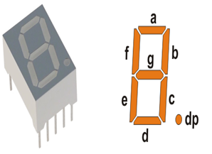
7 Segment LED Display:


Image result for 7 segment display gif


Hardware connection:


Program:

1st method:

/*
 * File:   3a_7SegmentLedDisplay.c
 * Author: Udaya Prakash Jayaraman
 * 7Segment led Display
 *
 * Circuitrcuit Connection
 * Com anode type 7Seg LED Display
 * RB0- a
 * RB1- b
 * RB2- c
 * RB3- d
 * RB4- e
 * RB5- f
 * RB6- g
 * RB7- h
 * Vcc- Resistor- COM
 *
 * Created on June 3, 2019, 2:23 PM
 */


#define _XTAL_FREQ 8000000

#pragma config FOSC = HS    // Oscillator Selection bits (RC oscillator)
#pragma config WDTE = OFF        // Watchdog Timer Enable bit (WDT enabled)
#pragma config PWRTE = OFF      // Power-up Timer Enable bit (PWRT disabled)
#pragma config BOREN = OFF       // Brown-out Reset Enable bit (BOR enabled)
#pragma config LVP = OFF         // Low-Voltage (Single-Supply) In-Circuit Serial Programming Enable bit (RB3/PGM pin has PGM function; low-voltage programming enabled)
#pragma config CPD = OFF        // Data EEPROM Memory Code Protection bit (Data EEPROM code protection off)
#pragma config WRT = OFF        // Flash Program Memory Write Enable bits (Write protection off; all program memory may be written to by EECON control)
#pragma config CP = OFF         // Flash Program Memory Code Protection bit (Code protection off)

// #pragma config statements should precede project file includes.
// Use project enums instead of #define for ON and OFF.

#include <xc.h>
#include <pic16f877a.h>

void DELAY(unsigned int Count)
{
    unsigned int i,j;
    for(i=0;i<Count;i++)
    {
        for(j=0;j<1000;j++);
    }
}


int main() {
    /* Configure the ports as output */
    TRISB = 0x00;

    while (1)
    {
        PORTB = 0xc0;
        DELAY(100);
        PORTB = 0xf9;
        DELAY(100);
        PORTB = 0xa4;
        DELAY(100);
        PORTB = 0xb0;
        DELAY(100);
        PORTB = 0x99;
        DELAY(100);
        PORTB = 0x92;
        DELAY(100);
        PORTB = 0x82;
        DELAY(100);
        PORTB = 0xf8;
        DELAY(100);
        PORTB = 0x80;
        DELAY(100);
        PORTB = 0x90;
        DELAY(100);
        }
    }


2nd Method:


/*
 * File:   3b_7SegmentLedDisplay.c
 * Author: Udaya Prakash Jayaraman
 * 7Segment led Display
 *
 * Circuitrcuit Connection
 * Com anode type 7Seg LED Display
 * RB0- a
 * RB1- b
 * RB2- c
 * RB3- d
 * RB4- e
 * RB5- f
 * RB6- g
 * RB7- h
 * Vcc- Resistor(value based on led supply, approx 100ohms resistor)- COM
 *
 * Created on June 3, 2019, 2:23 PM
 */


#define _XTAL_FREQ 8000000

#pragma config FOSC = HS    // Oscillator Selection bits (RC oscillator)
#pragma config WDTE = OFF        // Watchdog Timer Enable bit (WDT enabled)
#pragma config PWRTE = OFF      // Power-up Timer Enable bit (PWRT disabled)
#pragma config BOREN = OFF       // Brown-out Reset Enable bit (BOR enabled)
#pragma config LVP = OFF         // Low-Voltage (Single-Supply) In-Circuit Serial Programming Enable bit (RB3/PGM pin has PGM function; low-voltage programming enabled)
#pragma config CPD = OFF        // Data EEPROM Memory Code Protection bit (Data EEPROM code protection off)
#pragma config WRT = OFF        // Flash Program Memory Write Enable bits (Write protection off; all program memory may be written to by EECON control)
#pragma config CP = OFF         // Flash Program Memory Code Protection bit (Code protection off)

// #pragma config statements should precede project file includes.
// Use project enums instead of #define for ON and OFF.

#include <xc.h>
#include <pic16f877a.h>

void DELAY(unsigned int Count)
{
    unsigned int i,j;
    for(i=0;i<Count;i++)
    {
        for(j=0;j<1000;j++);
    }
}


int main() {
    char seg_code[]={0xc0,0xf9,0xa4,0xb0,0x99,0x92,0x82,0xf8,0x80,0x90};
    int i;

    /* Configure the ports as output */
    TRISB = 0x00;

    while (1)
    {
        for (i = 0; i <= 9; i++) // loop to display 0-9
        {
            PORTB = seg_code[i];
            DELAY(100);
        }
    }
}


 If you have any doubts do comment, thank you.


LED On OFF using Pushbutton with PIC16f877a


GPIO Registers

PORTDirection RegisterNumber of PinsAlternative Function
PORTATRISA6 (PA0-PA5)ADC
PORTBTRISB8 (PB0-PB7)Interrupts
PORTCTRISC8 (PC0-PC7)UART,I2C,PWM
PORTDTRISD8 (PD0-PD7)Parallel Slave Port
PORTETRISE3 (PE0-PB2)ADC

Hardware Connection:

LED on off Control with Pushbutton using PIC16f877a Microcontoller in MP Lab
LED On Off Control with Pushbutton using PIC16f877a


Program:

/*
 * File:   2_LedOnOffWithPushButton.c
 * Author: Udaya
 * LedOnOffWithPushButton
 *
 * Circuit connection
 * RD6- Connected to LED as OUTPUT
 * RC0- Connected to Pushbutton/SPDT switch to on/off control
 *
 * Created on June 3, 2019, 2:23 PM
 */


#define _XTAL_FREQ 8000000

#pragma config FOSC = HS     // Oscillator Selection bits (RC oscillator)
#pragma config WDTE = OFF        // Watchdog Timer Enable bit (WDT enabled)
#pragma config PWRTE = OFF      // Power-up Timer Enable bit (PWRT disabled)
#pragma config BOREN = OFF       // Brown-out Reset Enable bit (BOR enabled)
#pragma config LVP = OFF         // Low-Voltage (Single-Supply) In-Circuit Serial Programming Enable bit (RB3/PGM pin has PGM function; low-voltage programming enabled)
#pragma config CPD = OFF        // Data EEPROM Memory Code Protection bit (Data EEPROM code protection off)
#pragma config WRT = OFF        // Flash Program Memory Write Enable bits (Write protection off; all program memory may be written to by EECON control)
#pragma config CP = OFF         // Flash Program Memory Code Protection bit (Code protection off)

// #pragma config statements should precede project file includes.
// Use project enums instead of #define for ON and OFF.

#include <xc.h>

void delay(k)
{                                //delay function
    unsigned int i,j;
    for(i=0;i<k;i++)
    {
        for(j=0;j<100;j++);
    }
}
int main()
{
    TRISD6 = 0;
    TRISC0 = 1;
    while(1)
    {
        if(RC0 = 1)
        {
            RD6 =1;
            delay(100);
        }
        else
        {
            RD6 = 0;
            delay(100);
        }
    }
   
}


PIC Microcontroller Software Setup MPlab

In this tutorial we will see how to setup a Mplabx project to generate .hex file for Pic16f877a

Pic16F877A MplabX Setup0.png

MPLABx Setup Steps

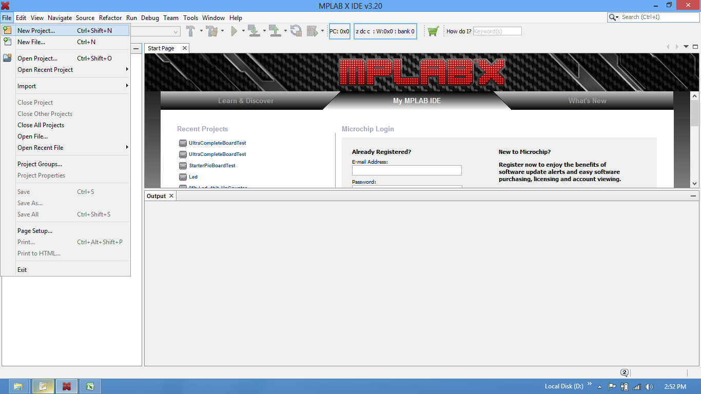
Step1: Open the MPLABx software and select the New project from File Menu as shown below.
Pic16F877A MplabX Setup01.png

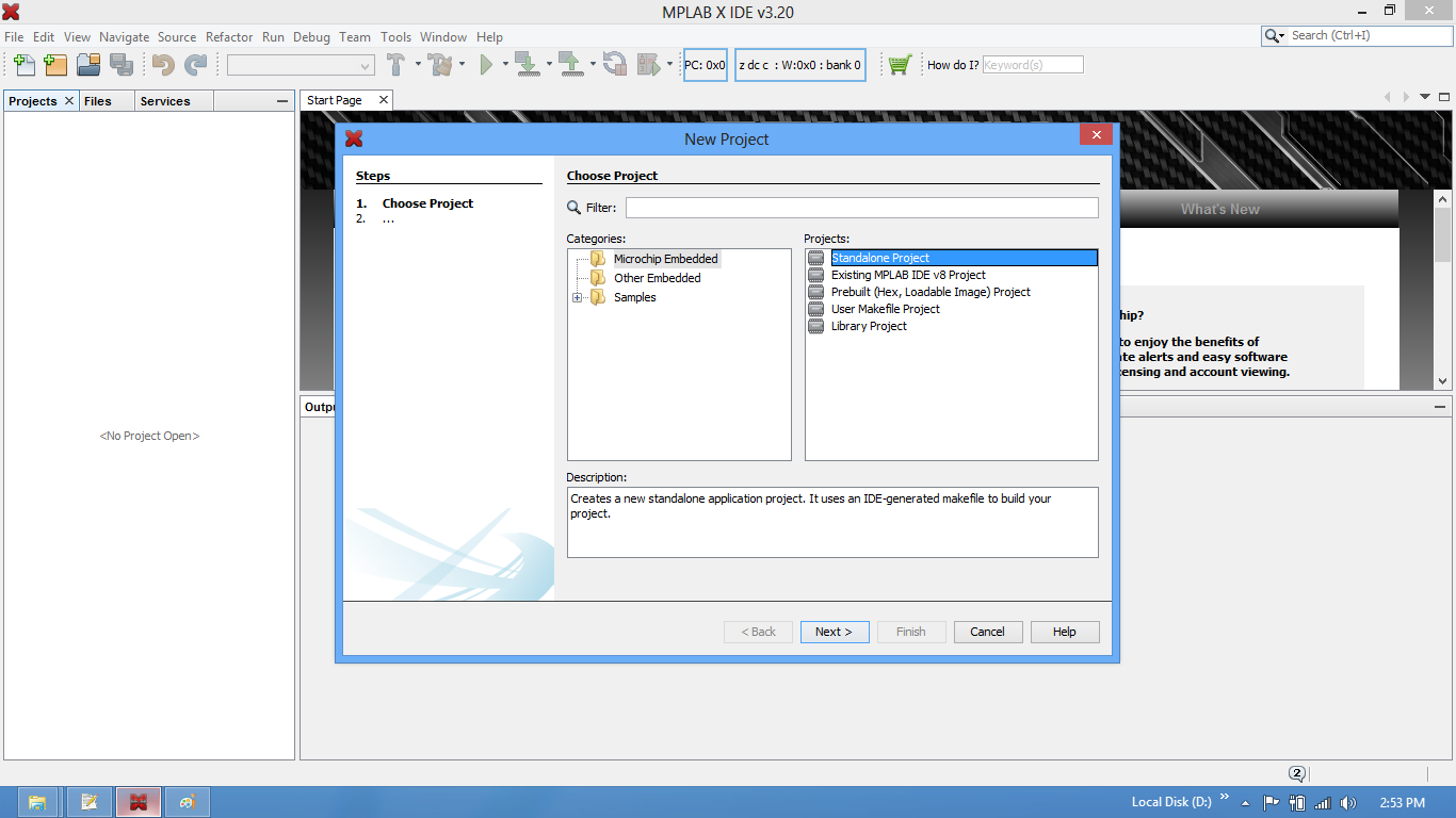
Step2: Select the Standalone option for the project.Pic16F877A MplabX Setup02.png

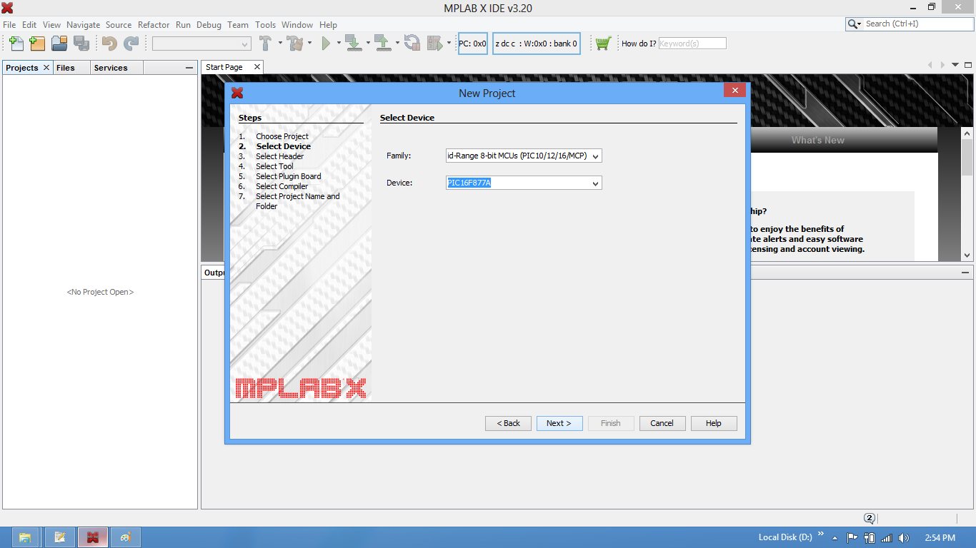
Step3: Choose the Controller(PIC16f877A) from the device drop down.Pic16F877A MplabX Setup03.png

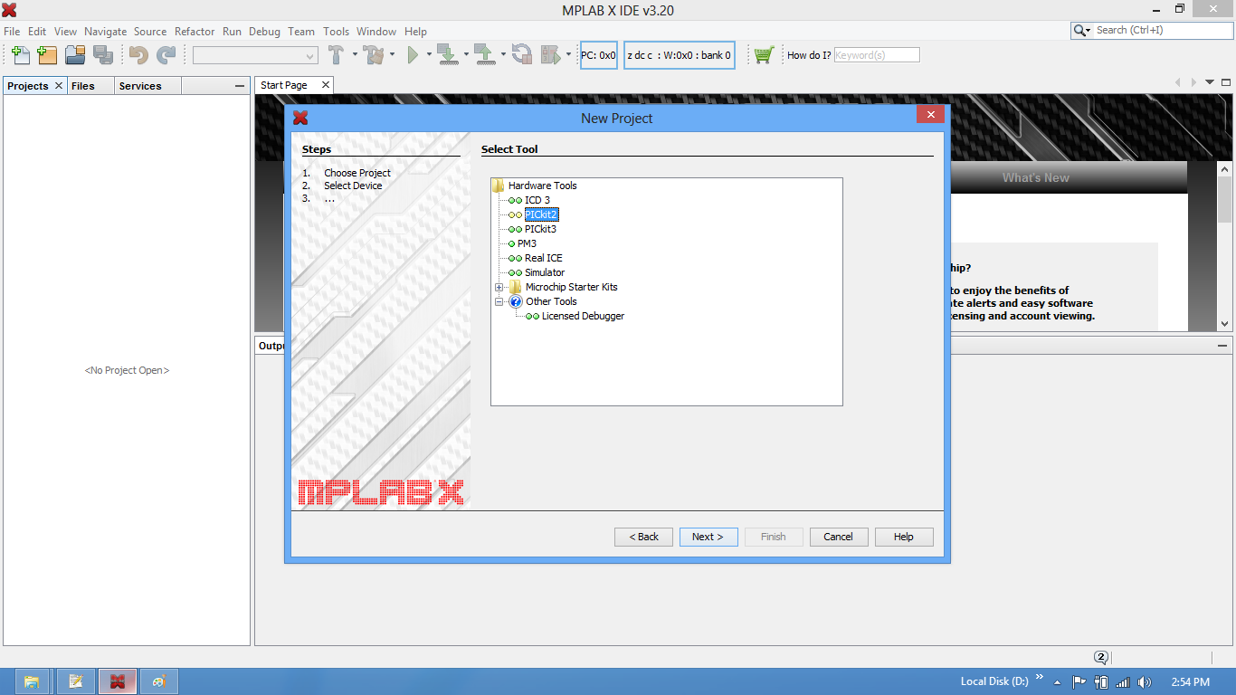
Step4: Select the required programmer. In this case it is Pickit2 or Pickit3.Pic16F877A MplabX Setup04.png

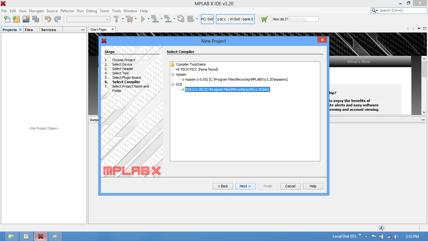
Step5: Choose the xC8/Hitech compiler which ever is installed.Pic16F877A MplabX Setup05.png

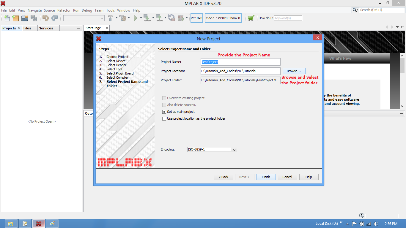
Step6: Provide the project name and project location.Pic16F877A MplabX Setup06.png

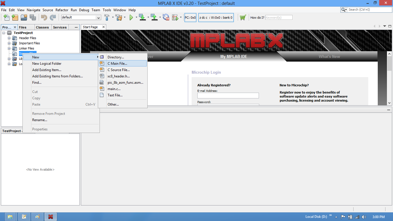
Step7: Now the required project is created. Create a new .c/main.c to write the code.Pic16F877A MplabX Setup07.png

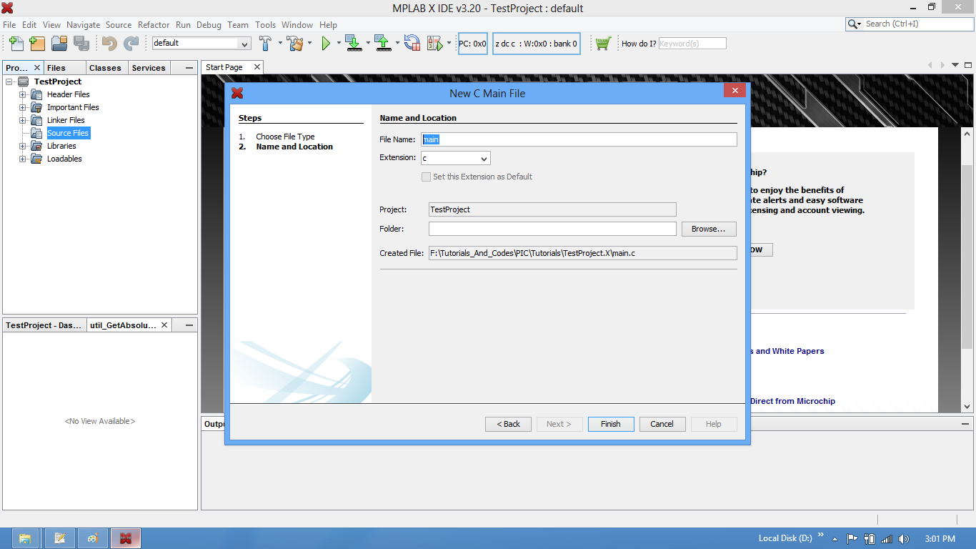
Step8: Save the file with C extension.Pic16F877A MplabX Setup08.png

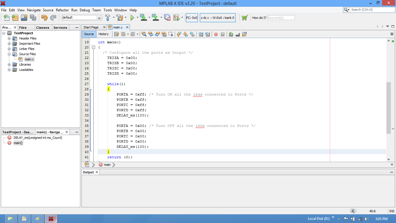
Step9: Type the code or Copy paste the below code snippet and save it

Pic16F877A MplabX Setup09.png 

 Program:

 /* Program By Udaya Prakash Jayaraman */
    #include <pic16f877a.h>
    void delay(unsigned int k)
    {
        unsigned int i,j;
        for(i=0;i<k;i++)
        {
            for(j=0;j<1000;j++);
        }
    }

    int main()
    {
      /* Configure all the ports as Output */
        TRISA = 0x00;
        TRISB = 0x00;
        TRISC = 0x00;
        TRISD = 0x00;

        while(1)
        {
            PORTA = 0xff; /* Turn ON all the leds connected to Ports */
            PORTB = 0xff;
            PORTC = 0xff;
            PORTD = 0xff;
            delay(100);
           
            PORTA = 0x00; /* Turn OFF all the leds connected to Ports */
            PORTB = 0x00;
            PORTC = 0x00;
            PORTD = 0x00;
            delay(100);
        }
        return (0);
    } 


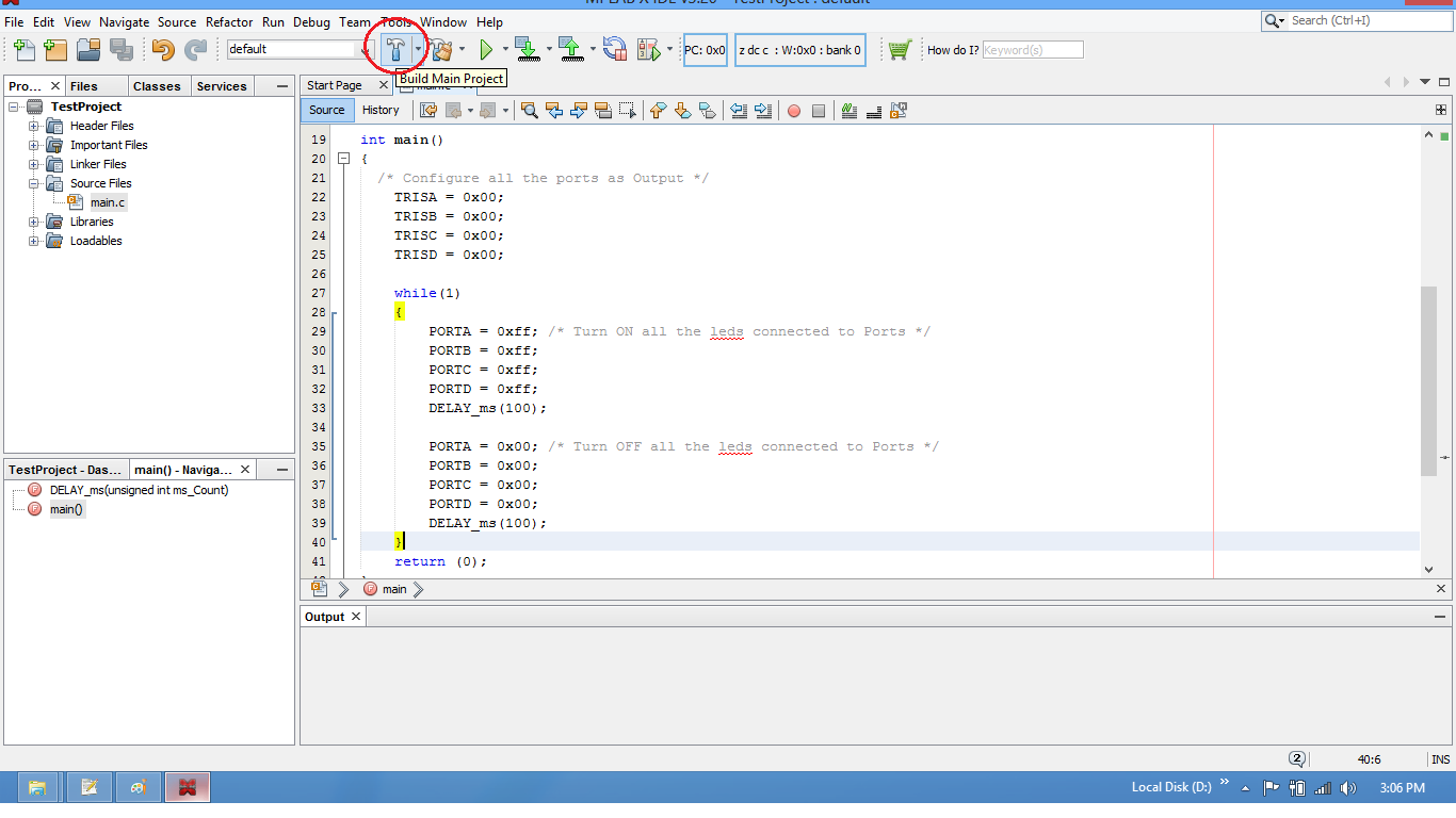
Step10: Build the project and fix the compiler errors/warnings if any.
Pic16F877A MplabX Setup10.png

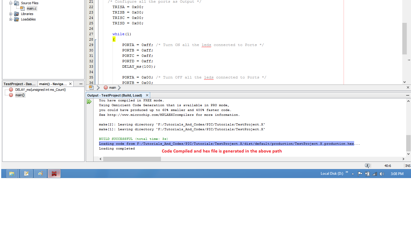
Step11: Code is compiled with no errors. The .hex file is generated.
Pic16F877A MplabX Setup11.png
Step12: Upload program to controller using pickit3